Maggie/Electronics/Level1
De Wikidroids
Sommaire |
Documents
The documents of this card are available here
Quick description
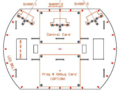
The level 1 card is part of the chassis. From the mechanical point of view, it makes the junction between the left and the right aluminium bars (as the level 2 too). It supports the Prop and debug cards.
Electrically, the level 1 card includes the led belt, the sharp sensors, and their wiring, and the wiring to the gyro card.
LED Belt
The led belt is composed of a 5v regulator, 4 shift registers with latch, and 32 leds.
The regulator is needed because the current needs for all these leds exceeds the current available from the prop card regulator.
The registers (U2 to U5) are shift registers with registers. This permits to shift the data via the DATA and a CK line. When the data is ready, the LOAD pin goes briefly high, so the output registers take the new value that was just shifted.
D1 to D24 are the led belt, the leds are spaced at 15° angles all around the level 1 card. The remaining 8 LEDs are just an auxiliary display, in form of a LED bar.
Sharp sensors
The sharp sensors are mounted vertically, so they need some hold mechanics. This is done by making little PCBs that are put vertically and just soldered in place onto the level1. Note that a 10uF tantalum cap is put as near as possible to the sharp. These sensors take big current pulses, so they need a good power supply.
This PCB has milled pins that are simply soldered in the holes on the level 1 PCB, like each other through hole component !! The little PCB on the right serves as rigidification for the 3rt plane. It is soldered behind the sharp, and also in contact with the level1.
There are 3 sharp sensors. The S2 is not implemented, because it is at the same place that the prop card. We can either place the prop card on higher braces, so that the sharp can be put under, or we can put the prop card at the rear location, and keep the front card location unused.
The sharps and the gyro signals are routed to J3, which is interfaced straight to the prop card (analog inputs).
Gyro
The gyro was ment to be screwed over the level 1 card, but since the Acceleration sensitivity problem, it is fixed under the center of the bumper.
