Maggie/Electronics/Debug
De Wikidroids
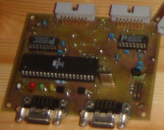
The debug card is needed to reprogram the main microcontroller (ISP), but it has a few other functions. This PCB is not needed in the robot itself ! We could imagine to put it out of the robot (at the other end of the umbilical cable for example.)
But it is very convenient, for a lot of reasons to install this PCB directly in the robot.
The debug card is connected between the bus and a target card. In Maggie, the target card is the prop card. The debug card isolates the UART ant the JTAG part of the target. The JTAG is interfaced to a RS232 connector, via a microcontroller. The UART is interfaced directly to a second RS232.
The documents of this card are available here
Schematics
J2 is the connector linked to the target board. J1 is the connector to the rest of the bus. J1 and J2 are wired 1 to 1, except for the UART and the JTAG.
U1 is a multiplexer which switches the UART pins. If the input is "1" (normal state), the uart of the target board is connected to the debug RS232,and taken out from the uart of the bus. In the other state (in reset, or if JP2 is set), then the UART pins are wired to the bus. This is done because the Rx/Tx pins have a secondary function as MOSI/MISO when the reset is low, and the SPI function should remain on the bus (not be isolated).
U2 has the same function with the JTAG interface : when the reset is high (run state), the JTAG of the target is connected to the JTAG programmer (U4). The JTAG pins are shard with other interfaces (when reset is low, TCK becomes SCK, and TMS becomes PGD ...)
U4 is a atmega 16. it makes the interface between the JTAG and the PC (via RS232.). This microcontroller contains an official ATMEL firmware. The controller also controls the /RESET line through T1 and T2. This is needed as the reset is an open collector, and than with a fex reset LEDs on the bus, the sink current can be quite big, too much for U4 to directly interface this pin.
U3 is simply an electrical interface to the two UARTs. The ST232 is cheaper and better than the well known MAX232. It needs only 100nF capacitors, so this saves place on the PCB.
Programming he JTAG interface
There is a procedure for ptogramming U4 with the right firmware.
see the Evertool light procedure : Evertool light program procedure
you must have another AVR programmer to be able to program U4. With it you program a simple bootloader into U4. Then you plug J8 to your PC, and you simply tell AVRstudio to upgrade the JTAGICE that is connected to the COM port. This friendly software then loads the needed firmware into U4! With that you have an exact functionnal clone of the JTAGICE. Cool, and this will probably even be legal.
Using the JTAG programmer
Please see the AvrHW/JTAG#how_to_proceed page for a general description
I use the following command to program Maggie :
avarice --jtag /dev/ttyS0 -ep -f main.hex -D
--jtag /dev/ttyS0 : this is for using COM1
-ep : means "erase and program"
-f main.hex : the file to program
-D : Detach : this is for not staying in program mode.
I have the problem that on some computers the program starts immediately after programming while on some others, it needs a manual reset to start. I did not find out why, so let me know if you find something !
