Maggie/Electronics/Prop
De Wikidroids
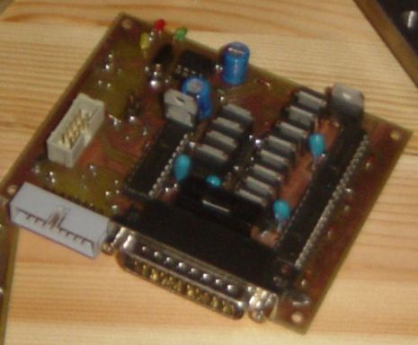
 The propulsion card contains the main electronics for Maggie.
In fact this PCB is the only one needed for making the robot run, you just have to add a gyroscope, two motors, and an accu.
The documents of this card are available here
Sommaire |
Microcontroller
The propulsion card contains the main microcontroller, an ATMEGA 128 clocked at 16 MHz (16 MIPS). This is up to now the only one on Maggie, excepted on the debug card.
The uC is interfaced to following peripherics :
6 PWM outputs (16 bits) are connected to 6 half-H-bridges, for the motor control. 6 Hall sensors inputs
4 analog inputs are provided, for the sharps and gyro.
The microcontroller is connected to the bus via all possible interfaces :
- The I2C for intercommunication to accu and option cards
- the UART for debug (printfs to the PC)
- The JTAG for programming and debug
- The SPI, for programming (not used when JTAG card is used)
- 3 additionnals pins, used for bit-bang to the LED Belt
Motor interface, and Power bridges
The two brushless motors need each one 3 PWMs with enough power capability. So for each motor, there are 3 half-H bridges.
See schematics of two of these 6 half bridges here . The two others are identical, just changing the component numbering: 23
The mosfets used are BUK7635-55A. I think 35A is enough ;)
This is of course oversized. The motors will draw each one max 10A if the max power is applied with the rotor blocked.
The mosfets drivers are the very good HIP4081 from intersil. These drivers make the boosted supply for the upper NMOS, with charge pump. The driver also handles the cross conduction disabling, which is a very useful feature in hardware!
The only drawback of these drivers is their supply voltage. This must be in the range 9-16V, which is tough to realise with maggie's 10.8V battery nearly discharged.
As one motor is driven by 3/2 HIP4081, the motor is always interfaced with two HIPs. This makes things difficult because the HIP have an internal cutoff. If one of the two HIP cuts, and not the other, the motor is partially powered, which is not very nice, but works. See the power supply issues...
Motor commutation
Perhaps many of you seek the brushless motor controller. There is no special purpose IC for that.
Instead, the microcontroller will poll the Hall inputs, and update the PWM outputs accordingly. This is done at 8kHz (on periodic interrupt). Of course this takes processor time, but this is the main reason for clocking it at 16 MHz. The controller is really able to do this.
As a bonus, the hall sensors serve as encoders, with 48 step per motor turn.
This makes a pretty cheap motor + encoder (55 E), cheaper than a 30W DC motor + encoder from maxon !
The commutation scheme of most brushless motor controllers is done with putting one phase on +, one on neutral, and one to ground. As i don't have the possibility to deactivate a half bridge in order to generate the "neutral", this is simulated by putting a 50% PWM on that phase !
For example : we want to applicate 20% of the battery voltage. The sensors are in a state that gives following commutation :
- The phase "X" must be "+"
- The phase "Y" must be "neutral"
- The phase "Z" must be "-"
For accomplishing this, the solution is to applicate the following PWMs :
- on phase "X" we applicate 60% (+10%)
- on phase "Y" we applicate 50% (neutral)
- on phase "Z" we applicate 40% (-10%)
This has one drawback : the PWMs must be synchronized, and quick enough so that the motor inductance filters them out.
This is done by using for one motor 3 PWMs issued from the same timer ! and by using a 32 kHz PWM (you don't even hear it).
Power supply
The prop card has one 5V regulator for the logics, and a 12V regulator for the mosfet drivers.
The regulators are tapped on a special line, after a diodeD4 and D1 This makes the power supply resistant to transcients on Vbatt (which is ery likely to occur)
However, for 10.8V - 14V supply, you must replace U3 with a wire, and replace D1 by a schottky diode. This is needed to keep the cutoff as low as possible !
If you use this card on 24V, then U3 is absolutely necessary !
There is a general power cutoff, built around U4. This one is supposed to cut off properly the 6 half bridges in case of low voltage. However, with the little room on the 10,4V battery, and bad precision of D5 as reference, this is actually set to 7V, so is not realy used(the HIP will probably cut before). However, the pin PG1 of the controller wil disable the H-bridges while reprogramming the uC, or on SW request, etc. This is an important feature !
Todo
- adding a 3v3 regulator for compliance with the I2C bus spec
- Adding pullups for the same compliance, as this is a "A" card, especially on SDA and SCL
- adding jumpers to deactivate this "A" behaviour
- better cutoff management