Microb Technology/2006/electronics
De Wikidroids
Sommaire |
To Begin
Schematics and PCB
! warning a bug has been reported !
General Motion Electronic
Our " vital " electronic is composed of two part :
- A numeric servo board
- An analogic power board
Both are link with a standard IDE 40 Pin cable.
Numeric card has for goal to manage motion of our robot, manage sensor, take decisions, etc... Power Board suply power to the numeric board and make motors turn (in fonction of the numeric board).
Have a look at this shema for a quick preview:

The Numeric Board
This board is equiped with many microcontrolors, 1 ATmega 128 and 1 ATmega 32, and 3 AT2313.
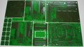
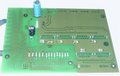
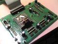
All PCB as Wurth Electronic send us.
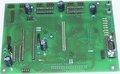
Our servo control in construction.
The ATmega 128 module.


The counter

AT2313 aim to count the pulses comming from the rotating sensor.
- The 4 ChannelXXX bits are the input of the both rotating sensor. Each sensor requier 2 bits.
- They have a 8 bit output (h1 to h8 pin) that display the position of the sensor. This position is coded from 0 up to 256, so you have to read it often or you will loose data.
- The AT2313 can manage 2 sensor. So you have to select the sensor that you want to read. This is done by using the select pin.
- The Xtal1 and Xtal2 is for the clock. One clock is shared for the 3 AT 2313. The frequency is 10 Mhz.
- The Reset pin is for the hardware reset of the chip. One reset system is shared for the 3 AT2313 and the ATmega32.
The ATmega 128

ATmega128 manage all the action of our robot. Servo Control functions are saved in this chip.
- The PWMX and SensX output pins are dedicated to the motor's command. The Sens select the rotation direction of the moteur and PWM output can regulate the speed. They use the internal PWM timer.
- BreakX is to enable or disable motor's power. This fonction is directly integrated in our amplification chips.
- The GX and FX input pins are for reading counters.
- LedX output pins are just debug signal. It can show us states of our robot.
- TXPc and RXPc are serial input/output for a remote controle with a standart computer.
- TXd2 and RXd1 are serial input/output for external interface respecting the standard."tof"standart.
- SDA and SDL are pins for I2C bus. It allow all interface between different controler and chips.
- TCK, TMS, TD0, TD1 are the SPI interface.
- CapteurX are inputs for sensors.
The Encoder Connector


- Just to remember how to plug our encoder.
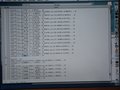
Debug Terminal
For debugging our electronic board we use a RS232 communication port.
Schnell ?

The Analogic & Power Board
Just some picture of the Power Board.
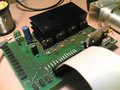
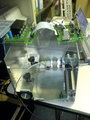
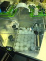
Our power board in construction.
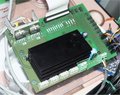
Now Power Board is finished.


Warning : If you had a look at our Power Board's SCH and PCB files, you may have noticed that numeric ground and power ground ar not link. It' s necessary to do it manualy. Just weld a wire between the GND's pins of the DCDC convertor.
The DCDC convertor
For 5V power suply, we use a Traco DCDC Convertor. It's a high output rate chip witch can deliver a 5V stable ouput with a large input bandwith, from 18V to 38V input. It' s connected directly to the batteries..
The LM12800T H bridge

- PwmX is a (0 - 5V) input pin. By changing the pwm width, the amplified output width change. So it change the speed of motors.
- SensX is a (0 - 5V) input pin. It set the rotation sens of motors by permuting boths amplified output.
- Break is a (0 - 5V) input pin. 5v = disabled. It disable motors. We added a pull-up to this signal so as to disable motor during reset time of AVR.
- Thermal Flag We dont use it.
- Out1 and Out2 are output pins. Wire it directly to the motors.
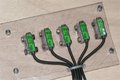
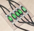
The Sensor connector

- This year we wanted to have a compact, strengh and secure connector. HE 4X2 connector is what we expected. Watch
shematic : if you plug it by the wrong way nothing append or damage your sensor.
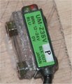
Sensors
Here is a small list of all sensors we use. They are "allready build" sensor.
Our color sensor. The "eyes" of this sensors is at the end of an optic-fiber.
The end of the optic-fiber.
Our ultra-subminiature infrared sensor.
Our infrared sensor slope for detecting holes.
Our infrared sensor slope calibrator.
Just to remember how to plug sensors. (Sorry if the picture is ugly)


What we use :
- 4 "UltraMiniature" infrared sensor for detecting holes (Max range : 3 cm)
- 3 "Miniature" infrared sensor for handling balls inside our robot (Max range : 12 cm)
- 2 "Miniature" infrared sensor for checking if an object is standing in front of our robot (Max range : 12 cm)
- 1 Color sensor for checking ball's color (Max range : 5 cm)
- 1 Starter system for starting the robot befor a match (Max range : 0 cm)
So a total of 11 sensors.
PIN assignation ATmega 128
- PWM 1 : front roller
- PWM 2 : left wheel
- PWM 3 : right wheel
- PWM 4 : not used
- Start switch : Connector 3 on Power Board
- Slop 1 : Sensor 8 on PD7 (through AtMega128)
- Slop 2 : Sensor 7 on PD6 (through AtMega128)
- Slop 3 : Sensor 6 on PD5 (through AtMega128)
- Slop 4 : Sensor 5 on PD4 (through AtMega128)
- Slop 5 : Sensor 4 on PF3 (through AtMega128)
- Front-left presence sensor (?)
- Front-right presence sensor (?)
PIN assignation ATmega 32
- PWM 1, on PD4 : Aspiration harness
- PWM 2, on PD5 : Evacuation harness
- Servo 1 (aspiration) on PA0 (through at90s2313)
- Servo 2 (loading) on PA1 (through at90s2313)
- Servo 3 (loading) on PA2 (through at90s2313)
- Servo 4 (evacuation) on PA3 (through at90s2313)
- Presence sensor (aspiration) on PC7 (sensor 14 - marked as 15 on the scheme)
- Presence sensor (loading 1) on PC6 (sensor 13)
- Presence sensor (loading 2) on PC5 (sensor 12)
- Color sensor (loading) on PC4 (sensor 11)
- Presence sensor (evacuation) on PC3 (sensor 10)
Communication system
Have a look to this diagram for a sample of our communication system

Bug Report
- A bug has bin found in our numeric card. The shared clock of AT2313 is not well wired. The output pin of "the master" 2313 clock has to be wired to the clock's input of the other 2313.
- The break2 should be controled by the ATmega32 instead of ATMega128
Beacons
The beacon system 2006 is willing to process the position quickly, and also detect the opponent robot. A laser will scan the environment, detecting bar codes on the beacons. The opponent beacon will be active (modulated IR)
It seems that we won't use the beacons on the robot this year.
Here is the architecture of the beacon (in french) :

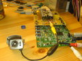
Some Pictures

Electronic's solder
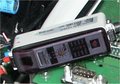
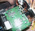
Mother board
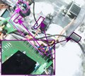
Power board
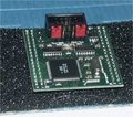
Camera board
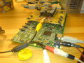
Camera board
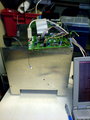
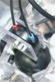
Power Board screwed on the robot's back plate.
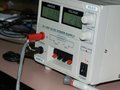
Zer0's power suply.
For fun : find the 1kOhm resistor ;-)
just to remember how to plug wires.
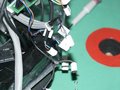
Now wires have number...


