Microb Technology/2008/Beacons
De Wikidroids
Current page: Microb_Technology / 2008 / Beacons
Sommaire
|
Preliminary beacons idea for 2008
Turning laser + catadioptrics reflectors
This is our first idea. Currently, we have not decided which is the best one...
Description
Here is a first draft about this idea :

And a perspective view :

Reminder
- Use the OPA 380 transimpedance amp for polarizing the photodiode.
- Use BPW34 photodiodes. Be carreful to use the one without the IR filter (it should no be black).
References
- Eirbot 2003 Beacons (french) : this system used a laser, but with active static beacons instead of catadioptrics reflectors.
- Balises CPLN Eurobot 2006 (french) : very interresting and complete link about beacons.
Turning Laser + photodiodes
This is another idea for 2008 (a bit more complex). Sorry for french terms in the schematics :)

Simple IR beacons
Like we did in 2004. It's quite simple, but it's not very efficient : we can only detect the angle (maybe a distance estimation too) that is not very precise.
Documentation of our 2004 beacons (in french)
Some considerations about beacons
Introduction
This small document describes quickly the mechanism for calculating the position of a robot in the following case:
- We have at least 3 fixed beacons at known positions.
- The robot is able to measure the angle between each beacon from its
point of view.
I'll try to have a geometrical approach, more than mathematical one. Sorry if what I wrote is not complete or not mathematically right.
I started to write this document on 2007-09-04, and I'll complete it when I'll have some time.
Beacons type
Since my first participation at Eurobot (in 2001), I've only seen two main kind of beacons for robot positionning:
- the ones that measure a distance (US beacons for instance)
- the ones that measure a angle (IR, laser, ...)
There are probably some other types, like camera based beacon, or radio beacon that can provide another kind of information. We can also imagine a system that can provide both angle and distance (see our first idea for 2008).
Also, some beacons don't aim to provide the (x,y) robot position on the area, but only to locate the oponent bot.
Our current idea for 2008 (it can still change ;) ) is to design a beacon that only provides the angle of the beacons, and we want to get an (x,y) position from it.
Theory: why do we need at least 3 beacons ?
What kind of position information is provided by 1 beacon ?
Huh..... nearly nothing for (x,y) position. We just know the direction of one beacon. So we can go in this direction to reach this point. For Eurobot, it is sometimes useful: for instance in 2002, to drop balls in baskets.
...by 2 beacons ?
This is a quite interresting question. If you read the [http://en.wikipedia.org/wiki/Inscribed_angle article about inscribed angle] on wikipedia, there is a big piece of the solution.
Before, here are some other interresting references:
- The circle
- Le cercle (FR)
- Théorème de l'angle inscrit (FR)
- Théorème de l'angle inscrit et de l'angle au centre (FR)
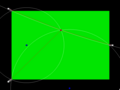
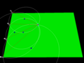
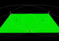
On the figure below:
- P and Q are the 2 beacons
- R is the robot
- O is the middle of PQ
- a is the angle PRQ
![]()
The known values are the angle a (this is what our sensor is able to measure), and the position of P and Q, which is fixed.
According to what we can read about the inscribed angle on wikipedia, we know that if a has a constant value, the robot R can be located on any point of the 2 circle arcs C1 and C2 (P and Q not included).
The first question is "how can we find C1 and C2 ? We know that the center of the first arc C1 (it's the same for C2 by reflection) is located on the mediatory of PQ. But where ? Still according to this same article, we know that the angle b is equal to angle a. So, we just have to find which point on the mediatory verify a=b.
It's also easily calculable:
d = l / 2.tan(a)
As a conclusion for this paragraph, we can say that with 2 beacons, we know that we are located on a circle arc... or more precisely on 2 circle arcs, but in our specific case (the beacons are on the border of the game area), it's easy to exclude the bad circle arc.
We still lack some informations to get our position.
...by 3 beacons ?
With 3 beacons, A, B and C, we can have 3 times the same case than above:
- Angle ARB
- Angle BRC
- Angle CRA
This means that R will be located at the intersection of 3 circles. Only 2 circles are necessary, because even if there are 2 intersection points between them, we know by definition that one of the intersection point is a beacon, so R should be the other :)
This is a good document about how to determine the intersection(s) between 2 circles (in french): [1]
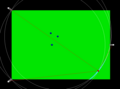
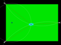
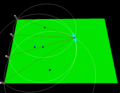
Below is an exemple with 3 beacons disposed as in 2007:
- The red point is the robot
- The blue points are the center of the 3 circles
- The red lines link the beacons with the robot

Can we always retrieve the position ?
No, it depends on the position of the beacons. Even if the measurement is very precise.
If there is a circle that can touch all the beacons, it means that we can be anywhere on this circle...

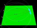
What is the influence of a measurement error ?
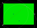
Below is an example with a measurement error of +/- 1 deg.
Instead of beeing on a the intersection of several circles, the robot is located at the intersection of several zones:

And with a zoom, we can see the different zones, and their intersections with other ones. If we consider an error of +/- 1 deg, the result of the position processing can be anywhere in the brightest zone.

What is the best disposition for beacons ?
As we saw in a paragraph below, some beacons disposition don't provide us the (x,y) position on the area even if the measurement is very precise. In the following images, the light blue zone represents the processed position of the robot, depending on angular measurement presision.
Disposition in D (3 beacons)
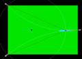
This is the case for a D disposition like below. If we are near the circle that touches the 3 beacons, it is not very precise. Else, it is quite good.
+/- 1 deg precision, the (x,y) precision is very good
+/- 1 deg precision, the (x,y) precision is about 10cm because we are near the undefined case
+/- 1 deg precision, the (x,y) precision is about 30 or 40 cm
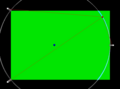
+/- 1 deg precision, the (x,y) precision is very bad...


If the angle precision is +/- 5 degres, it is quite correct in some places, but worst near the famous circle...
+/- 5 deg precision, quite good
+/- 5 deg precision, the (x,y) is correct regarding the angular precision
+/- 5 deg precision... huh we don't really know where we are.


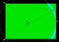
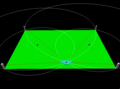
Disposition in I (4 beacons)
Let's try with another disposition, like 2003's disposition. It's very good if we are near the beacons, but it is not precise when we are far. The advantages is that there is no undefined point and we don't need a system to differentiate each beacon: indeed, the angle between the last beacon and the first is always > 180°, so we can easily recognize the first beacon. The disadvantage is that it is less precise in average.
+/- 1 deg angular precision, near the beacons, (x,y) position is very precise
+/- 1 deg angular precision, less precise
+/- 1 deg angular precision, further...
+/- 1 deg angular precision, precision is not very good


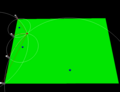
Disposition in X (4 beacons)
The best disposition in any condition, but not very easy to have in rules because the oponent can have beacons too ;)
+/- 5 deg precision
+/- 1 deg precision


Source code of the small application
The small application used to generate these pictures is a python script using python visual.
The source code is free : here
Beacon 2008, design
This section describes the chosen solution for the beacon system.
Summary
- This solution is close of "Turning laser + catadioptrics reflectors"
- The goal is to detect the position of the oponent bot, or the position of our robot
- There are 2 static beacons, each one is composed of a static laser+photodiode, and a rotative mirror (1200 rpm)
- There is a catadioptric reflector on the robot
- The 2 beacons communicate together using SPI
- One of the 2 beacons is the master, it processes the position and send it to our robot using Xbee
Description of elements
The following image shows the design of one static beacon. The laser is emitted on the rotative mirror, and can be reflected on the catadioptric reflector. The signal is amplified/filtered by the lens and received by the photodiode.

Electronics
![]()

