Maggie/Electronics/Level2
De Wikidroids
Sommaire |
Documents
The documents of this card are available here
Quick description
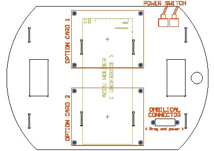
As the level 1, the level 2 card is part of the chassis. From the mechanical point of view, it makes the junction between the left and the right aluminium bars. It mechanically holds the accu, and two optionnal cards. It contains the power switches, the li-ion security electronics, and some interconnection stuff, like the ombilical connector, and a bus througout.
Accu electronics
The accu has integrated security components. These, in fact, do not open the circuit, but this task is done by power mosfets outside the accu block. This is rather curious, but Toshiba choosed this method.
Q1 is the overcharge security. It will be closed in normal operation, and opened when too much voltage is applied to the accu. In this case the diode contained in Q1 allows to discharge the accu, but not to charge it ! very clever electronics ! This feature is normally not necessary onto Maggie, because the accu will not be charged in the robot, but this security is necessary as the explosion risk is big in case of a bad power connection ...
Q2 uses the same concept : it is normally closed, so the accu can be charged and discharged normally. If an undervoltage condition is detected on one cell, the accu will put a logical 1 on pin 3, so Q2 will be open. It's internal diode allows charging. This is useful to prevent damage by discharging too much the accu.
The accu i2c pins are connected to the main bus. JP1 and JP2 can be used to break this connection. I actually did not even read the accu memory. It is not necessary for basic use.
Bus throughout
J6 and J7 are simply a bus througout. This is useful for making a mechanical pass through of the level card by the bus. So in fact it is not really useful. I actually have no option card on Maggie, so there is only a stub in J6 (for connecting the UART/JTAG loop).
Power switches
S1 is the main ON/OFF switch S2 permits to select either accu, or external supply through the ombilical connector. J2 can be used for adding a security switch (push to stop) J1 is the output of the main power. This is wired to the prop card.
Ombilical connector
The ombilical puts the external supply and two UARTS onto one very practical connector. I used a special connector, the same size as a DB15 but with two big power pins, and 5 normal pins. On J3 and J5, there are short cables soldered to the ombilical connector. In J4 we plug a flat cable that divides in two parts, with a DB9 at the end of each branch. This is connected to J7 and J8 of the debug card.
