Maggie/Electronics
De Wikidroids
Sommaire |
Detailed card description
Main organisation
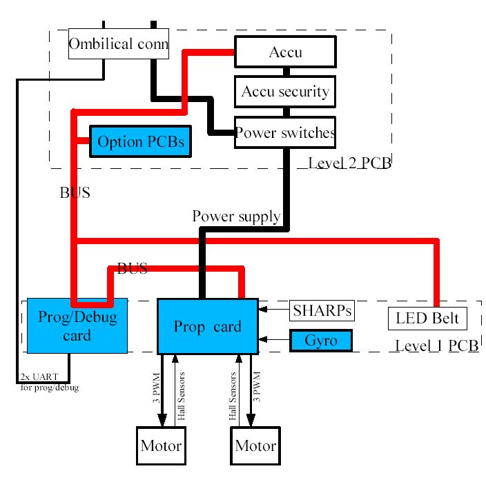
The electronics of Maggie is organized with an intercommunication bus.
Main interconnection scheme :
The two level PCBs make mainly interconnections, but some parts are directly put on them ! Electronics on the robot's chassis !!! (in white on the schematic)
The most important card of Maggie is the prop control card. This card has the main microcontroller, which runs the propulsion functions, polls the sensors, updates the motor PWMs, and updates the LED belt.
Power distribution
There are two types of power supply : The logic (regulated) and the raw battery voltage. The battery voltage goes from the battery to the prop control card. The bus then dispatches Vbatt and regulated voltage to all peripherials. The bus can not carry very much current, but enough for the led belt.
The motor power comes directly from the Prop card, through 3 half H-bridges for every motor.
Bus
The bus interconnection is barely a 16-pin HE10 connector. It carries a lot of signals :
- Vbatt, GND, 5v, 3v3
- JTAG communication used only from the debug card to the prop card. This serves for programming and debug purposes (GDB). The JTAG is interfaced by the debug card to an RS232 link to the PC.
- UART : used only from the debug card to the prop card. The prop card links this then to the ombilical connector, enabling logging on a PC for debug purposes. This second RS232 link is independant from the 'JTAG' one
- SPI : this is actually not used
- acessory pins : these are actually used by the led belt
- i2c communication : this should be the main card intercom bus, but as there is now only one active microcontroller on Maggie, it is only connected to the battery i2c memory, and the main prop microcontroller.
For a complete interface description of this bus, see Here.
